Introduction
A company named
Steorn has a magnet motor that they claim defies the physical laws of action/reaction. This motor recently went on display at a public location in Ireland complete with online lectures demonstrating the capabilities of the device.
There are number of informational videos on Youtube including:
How It Works
If you read the description on their
website they make it sound complicated…
“The time variant nature of Orbo interactions can be engineered using two basic techniques. The first technique utilizes a method of controlling the response time of magnetic materials to make them time variant. This is achieved by controlling the MH position of materials during permanent magnetic interactions.
The second technique decouples the Counter Electromotive Force (CEMF) from torque for electromagnetic interactions. This decoupling of CEMF allows time variant magnetic interactions in electromagnetic systems.”
Actually the principle is very simple. Take a ferrite toroid and wrap it with 50 -200 turns of magnet wire. If you bring a permanent magnet near the ferrite the field of the magnet will permeate and magnetize the ferrite causing an attractive force. If you send enough current through the coil surrounding the ferrite it will saturate and the attractive force between the magnet and ferrite will be reduced.
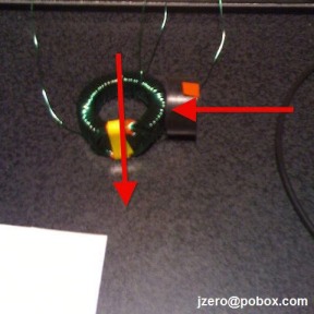
Their motor has a rotor with permanent magnets embedded. There are 4 or 8 ferrite cores are placed around the perimeter of the rotor. The North/South orientation of the magnets is not relevant because either pole can cause the ferrites to saturate.
Below is a closeup of the ferrites used in the demonstration.
The key thing to notice here is that Lenz’s law apparently does not apply in this interaction because theoretically the solenoid coil should keep all of its flux inside the toroid and create a shield against interaction with the magnet. The interaction appears to be happening only from the saturation of the ferrite material even with the fields of magnet and coil are 90 degrees to each other. If this were true then Steron would indeed have discovered a new type of electromagnetic interaction.
Real or Not?

Just how real is Orbo? That is one of the concepts I set out answer with some experiments. As a ZPE researcher it is my belief that conversion of the magnetic field into a usable electrical energy is possible and I began my testing of the Orbo system with optimism.
ZPE is not about creating something from nothing: It is about using the zero point of a wave as a means to transform other forms of potential energy like magnetic flux, heat, or particle spin into usable energy in such a way that entropy appears to be reversed. It is a science that is both suppressed and ridiculed and to see a company like Steron make it as far as they have seemed surprising.
I could have built an Orbo motor and made careful electrical and temperature measurements but I decided to take a simpler route and explore the basic physics of the system. My results provide evidence to indicate that:
- The magnets in the rotor do interact with the field from the coil.
- The field from the coil expands outside the toroid in certain conditions.
- Lenz’s law may still apply in this interaction.
Test Setup
Below is the device I used to obtain these results. It is a unique type of transformer with a primary wrapped around a ferrite and a secondary taped to the side.
Transformer specs:
Core: MnZn Ferrite, permeability=5000
Primary: 50 turns 26 AWG magnet wire
Secondary: 8 turns 26 AWG magnet wire
 |
| Saturable Transformer |
This is the circuit used for driving and measuring transformer characteristics. It is driven with a square wave from a signal generator. This signal goes to a driver that switches a power MOSFET. The Scope 1 probe measures current into the primary and the scope 2 probe measures current in the secondary.
I am including the schematic for the low-side MOSFET driver used. After some trial and error with other experiments I have concluded that this driver works very well and I encourage other people to use it. All the components in the driver can be obtained at Radio Shack.
There is also a permanent magnet (PM) used in the experiments. This magnet is cylindrical and has its poles oriented along the centerline.
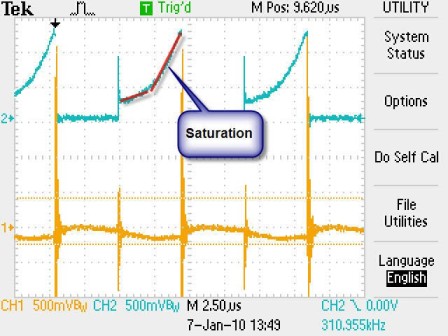
Initial Condition
In all of the following scope images the top trace is the primary current and the bottom trace is the secondary. When the primary is driven with 110Khz at 12V the core is brought into saturation. This is indicated by the increasing slope of the current.
The secondary shows almost no current (there is a bit because of slight magnetization and irregular winding). This indicates that the primary drive coil is shielding flux from reaching the secondary.
 |
| Case 1 |
Mode 1: The Magnetometer Effect
When a permanent magnet is brought close to the coil (case 2A) the flux from the PM is coupled with the flux produced by the coil. This flux passes the secondary and generates a current through it.
 |
| case 2A |
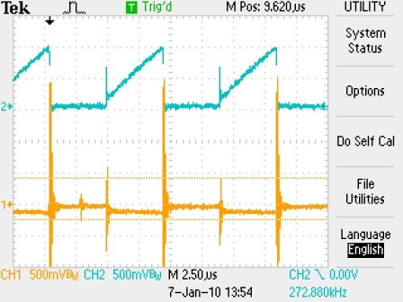
This is indicated by the primary and secondary in the scope trace below. Also notice that the primary no longer goes into saturation and we have a linear slope. This is because the primary coil is working against fields in the toroid in addition to fields in the magnet.
 |
| case 2A |
In case 2B we reverse the orientation of the magnet and the toroid responds in the opposite direction indicated by the scope trace.
 |
| case 2B |
 |
| case 2B trace |
In case 2C the magnet is positioned 90 degrees to the secondary. We can see that the primary does not saturate because the field is coupled to the PM but the secondary has little current. This is because the response is inline with the field of the PM and so no flux passes through the secondary.
 |
| Case 2C |
 |
| Case 2C trace |
The secondary responds to the PM with a significant amount of sensitivity. It is such an effective way of detecting a magnetic field that it was invented a decades ago as a toroidal “Fluxgate Magnetometer”.
 |
| Fluxgate Magnetometer |
When an external magnetic field is applied it causes one side of the toroid to saturate before the other. This creates an imbalance between the left and right side of the coils and causes an EMF to be induced in the secondary.
See these links for more information:
Mode 2: Deep Saturation
If the PM is brought close enough to the toroid then one end of the toroid will go into complete saturation and the response from the toroid will rotate 90 degrees. Regardless of the orientation of the PM the response is the same. This is because one side of the toroid is saturated leaving the coil to magnetize the other side.
 |
| Case 3A |
 |
| Case 3B |
We can see that in case 3C moving the PM to the opposite end reverses the flux through the secondary.
 |
| Case 3A and 3B trace |
 |
| Case 3C |
 |
| Case 3C trace |
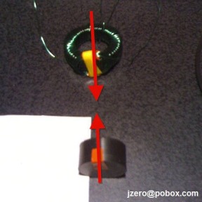
If we put the PM in line with the secondary as in Case 3D we measure nothing from the secondary. This indicates that no flux (or force) is changing between the magnet and the toroid.
 |
| Case 3D |
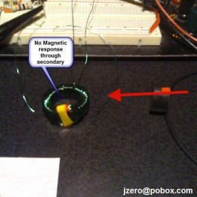
The Centerline Case
Something else to note is that when the magnet is aligned perfectly along the centerline of the toroid there is no force or magnetic interaction between the primary and the PM. This is because the effect that drives the Orbo motor relies on the asymmetry of the external magnetic field. In this case the flux from the PM is distributed evenly throughout all parts of the toroid.
 |
| Case 4A |
Conclusion
These results demonstrate interactions that are not commonly known in some circles. When the magnet is a sufficient distance from the toroid it operates just like a magnetometer and when the magnet is close enough to saturate one end of the core the other side induces a responding field.
One of the primary arguments implied by Steron’s claims is that the PM from the rotor does not cause a resulting back EMF in the coil. My results show that when coil and PM interact it is because of an asymmetry of flux in the toroid and that this always results in a field being extended outside the toroid that can interact with the PM. This indicates that although it is not immediately apparent Lenz’s Law may be alive and well in this system.


I worked with this effect years ago. a magnet is attracted to the steel of the toroid core. current is applied and the core saturates expelling the magnets flux and the magnet coasts away ready for the next attraction phase. this principle appears to make a motor with no back EMF and small scale low current tests apparently do not detect it but it is still there and will show up in a larger machine. This is how the back EMF works: if you measure the toroid coil inductance when the magnet is close to the toroid and then farther away, you will see that the inductance rises as the magnet moves away. a rising inductance, just like in a reluctance motor, causes back EMF. It works like this: when the magnet is close it causes a reluctance to the toroid flux. an applied current makes a given flux in the core. when the magnet moves away, the core flux rises because the reluctance is dropping. The rising core flux aligns new domains which induces an EMF that opposes the applied current. this is also the problem with the Lindermann Attraction Motor. Steorn/ Orbo will not find this problem until they make a useful output sized machine.
The concept of a changing of the core inductance is a good way of looking at it. We know that the energy stored in an inductor is given by
E=1/2*L*(I^2)
L=inductance, I=current
This shows that for a given current the energy stored is directly proportional to the inductance. One could say that as the magnet pulls away from the toroid the inductance in the toroid rises and so does the energy stored but as you said this comes at a cost of an opposition to the current.
I think one good analogy might be a figure skater who is spinning. Let’s consider that her rate of rotation is like the current rotating through the toroid. As she stretches out her arms she slows down because her moment of inertia increases. In the same way the current is reduced as the inductance is increased.
The figure skater is an interesting analogy. Back EMF caused by a rising inductance/falling reluctance is easy to miss when testing a model. In the case of the Steorn Toroid, the Adams Pulse, and the Lindermann Attraction motors,the back EMF is proportional to the amount of flux that is changing (rising) and therefore the amount of torque during the energized phase. If you test with only enough torque to keep the rotor spinning, then the amount of changing flux will be too small to produce a detectable Back EMF.
It’s very understandable that researchers could miss this effect. We all grew up with DC motor’s that you could spin and see the induced voltage/current on a meter. When the rotor is spun on the Toroid Motor, there is no Back EMF because the combined angles and directions that the flux cuts through the coil wires tend to cancel each other. It certainly looks like no Back EMF.
So, the common understanding of Back EMF is that caused by the Lorentz Force (a wire moving through a field) the other “voltage/motor action producing effect” is the Reluctance Force (magnet or steel interacting with an electromagnet)
Only in the last 20 years have reluctance motors emerged do to electronic switching capability. We didn’t grow up with these motors and so we are not too familiar with how this kind of Back EMF works.
Its as simple as this: if there is a resistance/reluctance to the flow of flux in the electromagnet (2and field or air gap) that decreases during the applied current phase, causing the flux to increase, then there is Back EMF.
Reluctance Back EMF is proportional to the mechanical force of the experiment.
With a high force setup, apply the amps,restrain the force, let the meter needle get steady, let the force make a fast motion…the needle will deflect downward showing an opposition to the current.
This test could put some good researchers back on a more productive track.
Sorry for the delay in response but I have busy with personal issues.
> “When the rotor is spun on the Toroid Motor, there is no Back EMF because the combined angles and directions that the flux cuts through the coil wires tend to cancel each other. It certainly looks like no Back EMF.”
It is an effect that you don’t really see in many motors. In order to produce a typical back EMF you need a changing magnetic flux through a current loop. In the case of a toroid its flux is completely contained inside because of internal cancellations. External fields don’t couple with it directly because of this.
What I noticed in my tests is that when certain parts of the toroid were saturated the internal cancellation was undone because only part of the toroid could contain the flux.
The Steorn hypothesis depended on the flux not coupling but they did not consider that it does couple when the toroid is saturated.
> “Its as simple as this: if there is a resistance/reluctance to the flow of flux in the electromagnet (2and field or air gap) that decreases during the applied current phase, causing the flux to increase, then there is Back EMF.”
That is a good way to look at it. I often view it in terms of forcing a change in flux vs. a change in permability. We learn in school that back EMF is a result of changing the flux through a current loop but in this case we are changing the permability which forces a change in flux. The permeability is typically a constant in field equations and people are not used to dealing with it as a variable.
The above test applies directly to the Lindermann Attraction Motor and indirectly to the Steorn and Adams motors. For these two motors, the applied current reduces the magnets attraction to the electromagnet core. When the meter needle is steady, the magnet is moved rapidly away from the electromagnet. The needle will deflect downward showing an opposition to the current.
In both cases the electromagnet reluctance drops causing the flux to increase which aligns new domains which induce an EMF (voltage) that’s acts against the applied current.
Think about this : in videos, the models of these 3 motors are never shown driving a load. The Back EMF is proportional to the load (force/torque) If you build one of these motors hefty enough to drive a load, then…you could detect Back EMF.
As Free Energy Researchers, when we have a good idea, we need to search hard for the problem. When you find the problem it allows you to move forward with your research. Think about all the time and money you waist if you think it works and it doesn’t.
> Think about all the time and money you waist if you think it works and it doesn’t.
When I first looked at free energy researchers I tried to distinguish between those who were honest and fraudulent. After 15 years of research I have come to realize that most of them fall somewhere in between.
I think many people start out with an honest objective but after a few years they see something that looks like it works and they fool themselves into living the fantasy that they wanted.
That being said there are some researchers who leave a legacy that looked promising followed a mysterious end to their studies. They may not be the ones making the noise but they are the ones to pay attention to.
Problems like this need to be a approached like a clinical trial. If you have a medicine that seems like it works great on monkeys you still have a long way to go before you know if you cured the disease.
I think your observation of the average free energy researcher is right. I have been studying magnetic effects for 21 years now trying to find a way to gain free energy using permanent magnets. I have always been able to find the problem in a design but I have not been able to find the problem in the design/concept presented below. Maybe someone can see something I’m missing.
THE PERMANENT MAGNET RELUCTANCE FREE ENERGY EFFECT
The machine embodiment of this effect is just a conventional reluctance generator with electromagnet stator poles but it uses magnets for the rotor poles instead of the usual steel poles. (not the small magnets placed on the sides of the stator poles for self excitation which is a common design. Using magnets for the rotor poles in a reluctance generator is nowhere on the internet)
OPERATION THEORY
When you turn the axle of the generator to pull the rotor magnets away from the stator poles it takes mechanical energy to do this. Then, when the magnets attract to the next poles the mechanical energy is returned. This is a break even situation. But…this action of pulling the magnet flux out of the electromagnet core also causes a changing flux which produces a voltage in the coil.
In a regular reluctance generator (plain steel rotor poles) the voltage is produced from the changing flux in the electromagnet core (after excitation). The applied mechanical energy works to pull the rotor/stator poles apart and that work causes the core flux to drop (change) and induce a voltage that pushes a current.
In this machine you have both electromagnet flux and flux from the magnet. While you still have to do the work of pulling the electromagnet flux apart, the work required to pull the magnet flux apart is returned when the magnet attracts to the next pole. The voltage produced by the changing magnet flux would appear to be a free voltage. additional voltage without additional work would be free energy. lawrencesprung@yahoo.com
8:51 PM
Larry,
I have some comments regarding your last post…
> The machine embodiment of this effect is just a conventional reluctance generator with electromagnet stator poles but it uses magnets for the rotor poles instead of the usual steel poles.
I don’t think it is significant whether the rotor pole is made of magnetized neodymium or regular steel with flux passing through it. The end result is the same.
> The voltage produced by the changing magnet flux would appear to be a free voltage. additional voltage without additional work would be free energy.”
I am not clear on this. Any changing magnetic flux should be subject to Lenz’s Law and so when you have a changing flux induce a current the current will produce a magnetic field that will oppose the motion of the rotor.
I think you may have better luck if you investigate the effects of scalar electric potential on magnetic induction.
Also, do you have theories about the significance of a Bifilar Coil? Floyd sweet used it to collect energy from his “positron current”. The bifilar coil cancels out magnetic induction but in the presence of a nuclear excitation field it could become a negative oscillator.
For example, Paul Brown was able to build a negative oscillator from a radioactive material. Perhaps there are non-radioactive ways to accomplish this?
There is more to this than it first seems.
> when you have a changing flux induce a current the current will produce a magnetic field that will oppose the motion of the rotor.
This is exactly my point. When the rotor magnet is pulled away from the electromagnet, the mechanical energy required to do this is converted into electric energy which agrees with Lenz’s law. But also, when the magnet attracts to the next upcoming steel pole (current off) mechanical energy is also returned.
It looks like 1 unit of mechanical energy is applied and 1 unit of electric energy is returned and also 1 unit of mechanical energy is returned.
The central thing going on here is that when a magnet is pulled away from a steel electromagnet pole, two things occur:
1. The applied mechanical energy is stored buy moving the magnet into a position of potential energy (which is returned when the magnet attracts to the next pole)
2. The applied mechanical energy is converted into electrical energy.
The process of pulling flux out of a steel core is common to both storing energy and converting to electric energy.
We know that the mechanical energy must be stored because it absolutely can be recovered when the magnet attracts to the next pole.
we know that the changing flux when the magnet is being pulled away from the steel core must also produce a voltage in the coil.
So…if it is not possible to get two things for one, than what is really going on here ?
Larry,
The forces acting on the rotor are a combination of the momentum of the rotor and the magnetic field acting on it. So we have:
(Force on rotor) = (force from field) + (force from rotor momentum)
as an equation of energy we have:
(Total energy of system) = (mechanical energy) + (energy from field)
Let’s assume that we have a motor with some perfect hypothetical conditions. The rotor travels at only one speed, the coil has no resistive losses, the rotor has a perfect bearing, and the coil is connected to a capacitor that is perfectly matched to the speed of the rotor.
In this hypothetical motor we could give it a spin and it would continue spinning forever because:
1. Energy from the rotor would induce current in the coil
2. the current in the coil would be used to charge the capacitor.
3. energy would be stored in the electric field by the capacitor
4. the capacitor would then discharge and induce a current in the coil.
5. The coil would produce a magnetic field.
6. The field would and produce a force on the rotor.
7. The cycle would repeat at step 1.
Such a motor would continue spinning forever because there would be no energy losses. The problem is that any losses like resistance in the wire would cause it to slow down until it stops.
When you consider the balance of forces in the motor it will only keep spinning unless the energy returned by the coil is the same as the energy induced in the earlier step.
Most physicists ridicule the concept of a system that would return more energy then it consumes because they are taught about conservative fields. The energy of the fields mathematically translate to a landscape of potential energy.
it would be like saying that if you slide down a mountain by 2 different zero friction paths then one path would contribute to your momentum more then the other. Most people accept that the elevation alone is enough to determine the potential energy.
One of my areas of research is to show that the situation is not quite that simple and that while I agree that momentum is always conserved there are different types of momentum denoted by grades according to the laws of geometric algebra.
Grade 1 is linear, grade 2 is angular or circular, grade 3 is toroidal, and I am not yet sure what grade 4 is but it should exist in 4D spacetime because it is a pseudovector. These grades of momentum are interchangeable under certain conditions.
I believe it is necessary to have analytical tools like this. To go without it would be like trying to build a house without a hammer. You need the analytical tools to break down space/time into components and see its parts working.
It is actually quite easy to see the back-emf from saturation ferite toroid: just power the toroid coil with a DC-current source just up to saturation and measure the voltage when changing the external magnetic field.
Also, there is actually a changed attraction between the ferite toroid and an external magnet when the toroid is saturated (case 4A), but it is very small: you have to add the magnetic vectors to calculate the saturation, derive the relative permeability for that, and then calculate the changed magnetic reluctance path for the permanent magnet. When done so you will see that the force only changes significant on (very) small distances (depending on the configuration: e.g. ~16% for a total airgap, this is including “return path”, of 1mm).
I tested this and it became appearent that a ferite core with a relative permeability of 5000, still has a permeability of about 50 when ‘completely’ saturated (H=1200A/m).
I understand that you can see back-emf if you power the toroid with DC. The problem is that the timescales are in milliseconds and it is much easier to work with a square waveform.
I agree that force between the toroid and permanent magnet changes when the toroid saturates and I observed similar results. Good work on calculating the changed reluctance path.
I rarely get visitors who are able to calculate the toroid inductance from the material and dimensions. I have some good notes on how to do this and I may post them at some point.