Concept
I have decided to do independent verification of some of the work done by Dr. Ronald Stiffler. I was searching around for “cold electricity” and I stumbled on his website http://www.stifflerscientific.com. It showed an interesting circuit where a single wire connection could be used to power an LED or neon lamp in a current loop.
Being a EE I was taught that it takes a positive and negative wire to transfer current so this grabbed my attention with thoughts of Tesla’s radient energy and single-wire power transmission.
To demonstrate the basic concept we have a signal generator connected to a loop with 2 1N4148 Schottky junction diodes. There must be 2 diodes and other types will not work. These come in a glass package, cost about 5 cents, have very low capacitance, and extremely fast response.
In the image below you can see the positive of my signal generator connected to the inductor. The antenna is a loop of about 1.5 ft of wire.

The frequency 8.9 mhz brings maximum power after adjusting the pot to 1.2K ohms. The calculated power consumed by the LED and pot is about 72mW.

The 22μH inductor is needed for imedance matching. Dipole antenna theory tells us that at this frequency our wire would need to be tens of meters for the capacitive and inductive effects of the antenna to be balanced. At shorter lenghts the signal is capacitave and we construct a shortened dipole by adding an inductor.
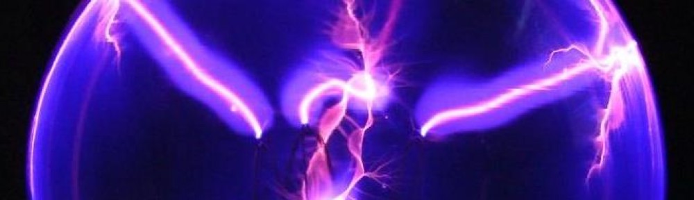
Ultra Wideband Generator
Telsa’s radient energy concept used spark gaps that generate signals with very high bandwith content. This is useful because the additional bandwidth carries more energy and results in more power transfer. The design below is based on Stiffler’s SEC exciter.

In the example below you can see that I have added a heat sink to the transistor and you can see that blue variable inductor.

This generator does its job well. The image below shows sharp peaks at 110V.

One big problem I had was that RF was being reflected back into the power supply. This caused the voltage reading to show anywhere from 0-30V when it was set on 12V. The common mode choke reduced this effect. The following image shows my common mode choke constructed by wrapping the DC supply leads about 10 times around a ferrite toroid.

You can find chokes like this around the power cords of many electronics in your home that shield them from EMF in your wiring. They work like a transformer where the primary and secondary cancel instead of induce current. Any current that is common to the leads will be cancelled.
Single Wire Coupling
The following is an example of single wire power transmission using the UWB generator outlined in a previous post. A single wire is attached to the UWB generator to illuminate the LED. When you start tuning the UWB circuit using the variable inductor you will find a number of harmonic frequencies at which the LED illuminates the brightest. While you do this tuning you should also tune the pot to avoid burning out the LED. You can connect multiple LED’s in series if you want.

The pot in this example is tuned to 121 ohms to avoid burning out the LED. The UWB generator is tuned to 2.9 Mhz. The power transferred in this example is estimated to be about 148 mW. In other tests the generator was shown to power over 9 LED’s using this method. In the image below you can see the white wire is a waveguide that carries the signal to the receiver that is completely isolated. The orange wire is an improvised antenna.

Some interesting observations:
- The LED does not illuminate without the antenna or something to carry the RF. Without the antenna a human hand is able to conduct the RF and illuminate the LED.
- I notied that a series as opposed to parallel reistance has little effect on the LED output. The voltage seems to be determined by the power consumption which explains why a neon lamp also works even though it demands much higher voltage.
- I measured the power going into the UWB generator and I observed additional current draw when the LED is illuminated. Even though the circuit is not closed some power is being transferred from the transmitter to reciever.
Grounded Coupling
In this example I show wireless power transfer where current is being drawn from an earth ground connection. This reminds me of a Tesla patent where the reciever has an antenna connected to earth ground.

Tesla’s example has a condensor (aka. capacitor) that could be impedance matching the antenna. My example below uses inductors but if the antenna had extra inductance then a capacitor would have been needed to match the impedance.

In the below example you can see power being transmitted between the UWB generator and the reciever that is connected to earth ground. The white wire attached to the generator is an antenna that is impedance match with an inductor like a shortened dipole.

The copper wire attached to the reciever is connected directly to the earth ground of my 120V A/C power outlet.

I am a designer. Very interested to talk to you about this work.
See my work here – http://www.ben-dror.com
Please send me an email asap.
Hello! I read your post after finding it on yahoo. It was very helpful and so I was hoping you could highlight some further content. Keep Posting Thankyou.
Fun !!
FWIW, You’ve just re-invented the ‘crystal set’, and its ‘Science Fair’ cousin, the simple, usually one-transistor radio powered by tuning a second LC circuit to powerful local AM station…
ps: Stiffler link is dead…